
ARTICLES

Once the machine tending process is defined, tool count, orientation, reach, payload and pneumatic integration all influence how the grippers are configured and connected to the robot.
A machine tending process can be clear at application level and still become difficult when the tooling is selected, configured and installed. The robot may need to carry the next raw part while removing the finished component, reach through a restricted machine opening, clean the fixture between cycles and do all of this without exceeding the available payload or space inside the machine.
Those requirements affect more than the choice of gripper. They influence how many tools are needed, how those tools should be positioned, how far the gripping point sits from the robot wrist and what has to be integrated around the tooling to operate it.
If the overall application is still being defined, start with what matters before selecting a robot for CNC machine tending?
Start with the part-change sequence
The choice between one or two grippers starts with how the robot needs to exchange parts at the machine.
With one gripper, the robot removes the finished component, leaves the machine to place it in the output area, collects the next raw part and returns to load it. With two grippers, the robot can arrive already carrying the next raw part, remove the finished component and load the new one before leaving. This reduces the movements required between machining cycles and can shorten the time the machine sits idle.
A second gripper also changes the physical tooling setup. The robot carries more weight, the tooling occupies more space at the wrist and both tools need enough clearance to enter the machine and reach the workpiece. The cycle-time benefit therefore has to be considered together with machine access and available robot payload.
If the gripping technology itself is still being defined, we cover that separately in CNC Machine Tending: Electric or Pneumatic Grippers.
Let the machine determine the tooling geometry
A dual-gripper setup does not have one standard layout. Tool orientation depends on how the robot can approach the chuck or fixture, the available clearance and the movements needed to exchange parts.
When a dual-gripper arrangement is built using custom mounting components, the assembly can become bulky and heavy. That additional weight reduces the robot's available payload for the grippers and workpieces, while the size of the mounting structure can make access to the machine more difficult.The pneumagiQ range from Impaqt Robotics combines pneumatic control and distribution with the mechanical interface between the robot and its tooling. Valves, control electronics, sensor connections and air blow-off are integrated at the robot wrist, with a single compressed-air line supplying the interface. The range also offers different tool orientations, reach and load capacities, allowing the pneumatic interface and mounting configuration to be selected according to the application.
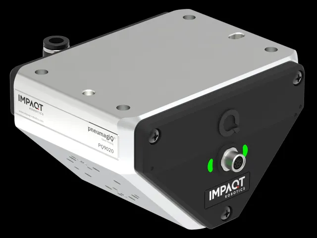
A 90° arrangement positions two grippers perpendicular to one another and can work well where the robot has enough room to rotate between loading and unloading positions. For example, in a CNC lathe where the robot arrives carrying a raw blank, removes the finished component and then reorients its wrist to load the next part, the pneumagiQ PQ90 provides this configuration for loads up to 5 kg. If the same arrangement is suitable but the combined weight of the grippers and workpieces is higher, the PQ9020 offers a 90° configuration with a capacity of up to 20 kg.
Another machine may be easier to access with the tools positioned opposite one another. Where the approach direction and available clearance favor this arrangement, the pneumagiQ PQ180T provides a compact 180° tandem configuration with a rated capacity of 10 kg. The dimensions of both grippers still matter, particularly when the unused tool must pass close to the machine opening or fixture during the exchange.
If the fixture sits deeper inside the enclosure, the distance between the robot wrist and gripping point can become as important as the angle between the tools. The pneumagiQ PQ180 provides a 180° arrangement with a 200 mm extension, positioning the grippers further from the robot wrist. In some applications, this additional reach could make it possible to use a smaller robot rather than selecting a larger model primarily to reach the workpiece, provided the robot can still handle the resulting load and complete the required movements.
For applications requiring only one pneumatic tool, the PQ0 provides a compact inline configuration.
Whichever configuration is selected, the robot must be able to handle the complete tooling assembly, including the grippers, interface and workpieces. In dual-gripper applications, this may mean carrying both raw and finished parts at the same time. Additional tool reach also moves the load further from the robot wrist, so payload, center of gravity and inertia need to be checked alongside machine clearance.
Design the pneumatic setup around the tooling
A pneumatic gripper needs compressed air and control. The tooling may also require sensor connections, and machine tending often uses air blow-off to clear the workpiece or fixture between cycles.
If the valves and control components are located away from the robot wrist, air tubes and sensor cables need to run along the robot arm to the grippers. Adding a second gripper can increase the number of connections, while cleaning introduces another air function. The tubes and cables must also be arranged to follow the robot's movements as it enters and leaves the CNC machine.
With pneumagiQ, the pneumatic functions are handled at the robot wrist rather than through separate valve assemblies and connections distributed around the robot. Sensors on the tooling can connect directly to the interface, while the integrated blow-off can be used to clean the workpiece or fixture during the part-change sequence. This reduces the amount of tubing and wiring that needs to be routed along the robot arm, particularly when two pneumatic tools are used.
The gripper remains an application-specific choice, depending on the workpiece geometry, gripping force and handling requirements. pneumagiQ is brand-agnostic, giving integrators the freedom to select pneumatic grippers from manufacturers such as SCHUNK, Zimmer Group, SMC, Festo, Camozzi, DESTACO and PHD, among many others.
For a closer look at the pneumatic interface itself, see The secret to smarter pneumatics: why pneumagiQ is a game changer.
Keep the recurring setup consistent
When the same machine tending concept is repeated across several CNC machines or adapted for another part family, the pneumatic setup becomes another part of the work that has to be repeated. A custom setup may be manageable when it is built once, but across several cells, valves, fittings, tubing, sensor connections and blow-off still need to be selected, mounted, connected and commissioned, even when the underlying pneumatic functions are similar.
The machine, workpiece, robot and gripper may differ from one project to the next. Keeping the recurring pneumatic functions consistent can reduce the integration work required for system integrators and make it easier for manufacturers to adapt a similar setup to another machine or part family.
Planning a pneumatic machine tending setup?
If you are working through gripper layout, reach, payload or pneumatic integration, get in touch with our team.